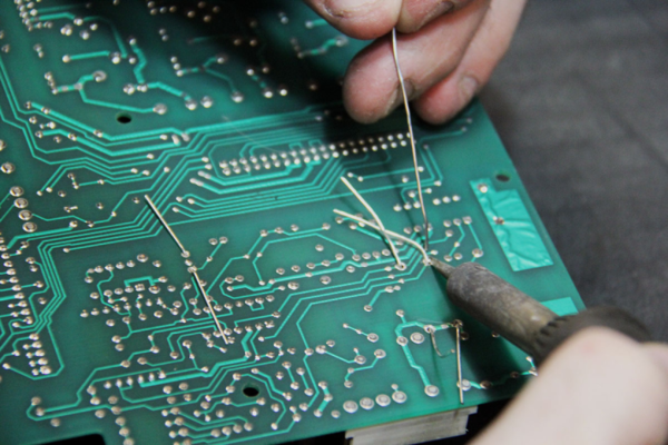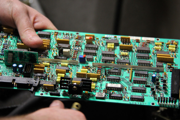
It often happens that a small part or poor contact is to blame for a malfunction of electrical equipment. If a visual inspection does not reveal the cause of the failure of the device, then it is necessary to test all its units.
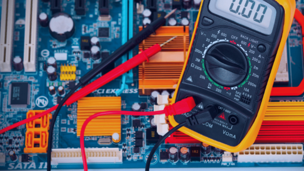
These actions allow you to exclude serviceable elements from the electrical circuit and find the cause of the breakdown. You can check all the components of the board and restore the performance of the equipment using a multimeter.
Initially, it is necessary to check the integrity of the loops and the quality of the soldering of the contacts. If no deviations are found, then all elements are checked one by one. For example, an inductor needs to be tested for open and short circuits in the winding. Resistor, diode, capacitor, microcircuit and other components for compliance with the nominal values.
Creating electrical circuits and tracing printed circuit boards is becoming more and simpler. Component manufacturers are integrating more and more functionality into products:
§ posting ready-made models
§ conventional graphic symbols (UGOs)
§ and entire circuits
§ sites automatically generating power supplies
§ filters, and much more
However, even when designing simple printed circuit assemblies, mistakes are found, often stupid and obvious.
Today we will not talk about DRC and ERC, they must always be done, and everything is more or less clear with them. Let's talk about human verification.
When you scroll through the layers in your board for the next "last" time before sending it to production, the picture is already so familiar that the eye misses mistakes. For verification, "second eyes" are needed - it's time to call another engineer.

When you are looking for someone with these "second eyes", - the circuit and the board are completely new, and everything unusual catches the eye. However, an unsystematic check does not guarantee a total review of dangerous places, which can lead to delays in debugging and additional iterations that are not provided for by the budget.
With the awareness of these limitations, we have introduced a list of checks that allows us to cut off the most common errors.
There are almost no highly specialized items on the list - we do a lot of various projects, and the list is universal. For all the difficult places in digital circuitry, there are checklists that are given by chip manufacturers.
As soon as the circuit or board, according to the author, is ready, he sets the task of checking another engineer (Reviewer) in Redmine. The reviewer, in addition to having knowledge and experience, must study the TOR and all additional project materials. All this takes a lot of time, which should be allocated at the project planning stage.
Having finished reading the documentation, you need to tune in the right way. Validation is about helping you achieve the best possible result. Before attacking with criticism, it is important to remember that the engineer tried to do his job excellently, "from the heart", and the task of the inspector is not to disturb this mood.

The reviewer copies the text of the checklist from the Knowledge Base into a comment on the task and then moves through the list, leaving his notes. Notations are used:
· "+" and "-" to state the passage or inapplicability of the item
· highlighting in bold for obvious errors,
Below is the text of the list from our Knowledge Base; comments for you are in italics. There are some items in the list that are specific to Altium Designer.
A multimeter is a universal measuring device that allows you to check radio components and measure voltages. This is a useful measuring instrument for both radio amateurs and craftsmen.
In multimeters, there are from 3 to 4 probe connectors. In 90% of measurements, only two connectors will be needed. These are COM and VΩ.
The black probe of the multimeter is always connected to COM. The default black probe is a minus, a common wire. That's why it's called COM.
To measure voltage, resistance or continuity of radio components, the red probe is connected to the VΩ connector.
By default, the plus is the red wire if you connect it correctly. The black probe of the multimeter is always a minus, and it is inserted into the COM connector, regardless of the operating mode.
First, you need to familiarize yourself with the technical data sheet of the device and study its capabilities and measurement limits.
When measuring, do not touch the metal base of the probes. If you check the details - this may affect the testimony; they will be false. And when checking high voltages, if you touch the metal base of the probes, you can get an electric shock.
If you do not know the approximate values \u200b\u200bof the voltage source, then you should always set the measurement limit of the device to the maximum.
Do not touch the metal base of the probes. Is it dangerous? As you can see in the photo, the multimeter shows 222 V., And that is why the limit of 750 V was chosen. If you put less, the device will show infinity and may fail.
To measure DC voltage, you need to switch the device to the icon V—.
Since the 18650 battery is measured in the above example, then for sure its maximum value cannot be higher than 5 V. Therefore, you can safely set 20 V if you are confident in the source and in your assumptions.
If, when measuring DC voltage, you see a minus sign in front of the number (-), then this means that the polarity of the source is reversed.
That is, the black probe, which is negative by default, is connected to the positive of the battery. And on the red probe, respectively, minus the source. Thanks to this, you can find out the polarity of an unknown source.
We swap the probes on the battery to the opposite, and now we know exactly where the battery has a plus and where a minus. This is a very useful feature of the DMM. Compared to the analogue, it is not damaged if the probes are mixed up in places, and you can accurately determine where the plus and minus of the voltage source are.
For example, to measure capacitance, you must first switch the red probe to another connector where the capacitor is indicated.
When measuring capacitances, the red probe should be on the plus, and the black one on the minus. And before measuring electrolytic capacitors, they must first be discharged. Otherwise, the measuring circuits can be damaged.
You can also measure direct and alternating currents. On the switch scale, the designations are the same as for voltage. The alternating current is A~, direct A-.
To do this, switch the red probe to the socket where mA is written. If you need to measure more currents, that is, already amperes, then the red probe switches to the connector where the amperes are indicated.
When such inscriptions as "20 A MAX 10 SEC" are present, this means that currents of not more than 20 A can be measured for no longer than 10 seconds. Otherwise, the fuse will blow.
All other functions of the multimeter depend on its functions, cost and manufacturer. It is possible to measure current frequency, h21e of transistors, capacitances of capacitors, etc.
The needles at the ends of the probes are very practical. They allow you to measure SMD parts. It is enough to solder ordinary needles to the ends of the multimeter. You can also make a pair of probes with alligator clips so that you can attach the probes to the measured wires or parts.
By continuing to use the site you agree to our privacy policy Terms and Conditions.
Recruit global agents and distributors Join us